
At about 4 am we lost power on V1 and remotely found the cabinet would not become ‘ready’. On-site it was quickly apparent that tube bias was not satisfied and looking over the schematics again I decided to quickly isolate the tube to know where I should start looking. As soon as I pulled the bias voltage lead from the tube HV junction box the bias supply came back up to normal (https://youtu.be/iqqVXn7s8aA), so my first thought was that we lost the tube to a cathode-grid short.
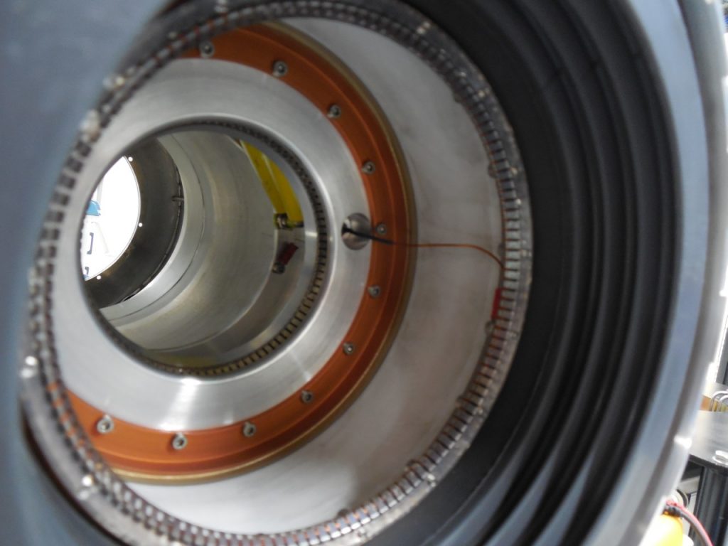
I called E2V and Harris to get some ideas on how I could test my theory and was informed that there were caps in the HV junction box as well as the input cavity that could possibly cause this problem. According to Harris there would probably be a 95% chance the tube was shorted and a 5% chance the caps were to blame. I called our Director of Engineering to get him spun up again for generating the paperwork for another IOT purchase from the UK and called E2V when they opened on the 6th to get two complete capacitor kits sent to us. In the meantime, I repaired a slow Ucatherm coolant leak on one of the tube supply line’s Hansen fitting (since I had the tube out) and attempted to test the caps in service. The caps appeared to be okay, but they are not in very accessible locations within the input cavity for the IOT (see below).
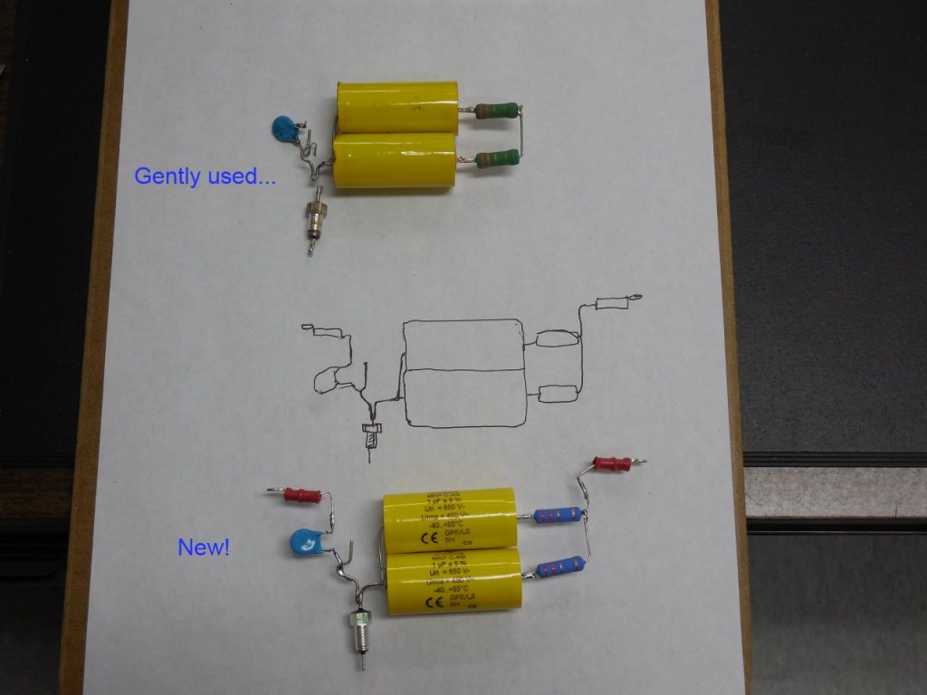
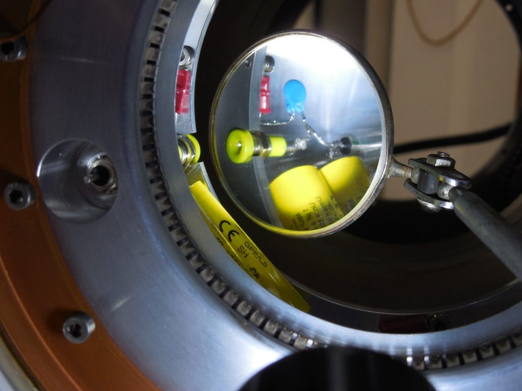
The caps arrived the morning of the 9th and I went about pulling out the old, fashioning the replacements to fit and putting it all back together (photos below). I must say I was genuinely (and pleasantly) surprised to see the bias voltage held when connected to the tube. I really expected that I’d be swapping out the IOT in a few days.
Once I had the parts on the bench I tested each individually and all checked out except the 1nF pass-through ‘stud’ cap. It showed no capacitance and appeared to bias like a diode.
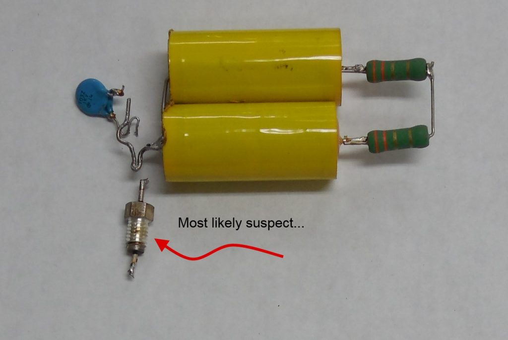
My guess is that somewhere around 140 volts it becomes less of a diode/cap and more of a passive conductor to ground.

I have a new list of (compact) tools I plan to buy now that this is done (does anyone make a right-angle soldering iron with a built-in micro camera and pincers?), but all-in-all it was a really good learning opportunity and I didn’t have pull all-nighters to further my education. 🙂