
For those of you that recognize the ‘Heathkit’ reference you get a cookie. Well done.
Unlike the Heathkits of yore I”m using some nice, mostly modern test gear here and servicing a fairly modern transmitter (circa 1998). This is one of those occasions where broadcast engineers get to leave the desk, the whiny news department and office politics to really hone their skills doing manly, gritty, thought-provoking, analytical, rocket scientist-like work that will separate them from the other mindless office drones they will have to return to later.
The back story; one of the stations I oversee here in the San Francisco market had an apparent failure of one of the IOTs (Inductive Output Tube) which, for those not familiar with TV RF work, is used as the final, high-power amplification device to bring a TV signal to a significant strength in order to survive being shot out of an antenna on the tower and over the air to lots of little rabbit ears across the horizon.
This Comark IOX (later sold to Thales, later sold to Thomson) analog transmitter uses two IOTs phased together we were able to stay on the air by routing the first tube to the antenna in order to maintain 50% of our nominal power output. The first thing we did after the station’s Chief Engineer suspected the IOT had failed was to take the tube and magnet frame out of the transmitter amplifier cabinet and apply a high-voltage potential to various elements of the tube to see how well (or poorly) it would handle the stress. This allows us to see that the problem really is the tube and not something else in the circuit which would cause a failure similar to a dead tube. Since these things cost around $35, 000 it is worth checking to be sure.
Since the IOT normally operated with ~30kV potential between its Anode and ground, we used a commercial power supply capable of 40kV (but low current) and hooked it up to the tube. We found that it would not hold the voltage and passed way too much current when we only put around 24kV on it. Time for a new tube.
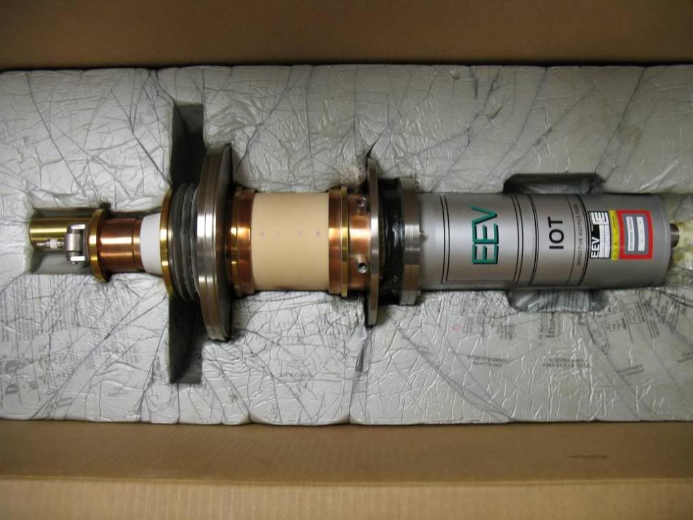
This is what an IOT looks like outside of the magnet frame. It’s a pretty amazing device that takes a beam of electron current created from about 30kV and makes 33kW of visual power! but, after about 77,000 hours and nearly 10 years of use it was tired of life…
Well, out with the old, and in with the new:
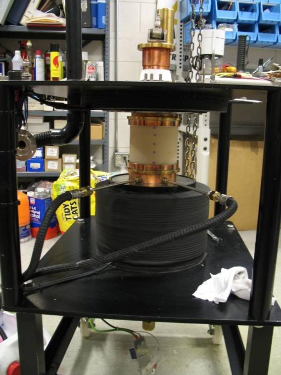
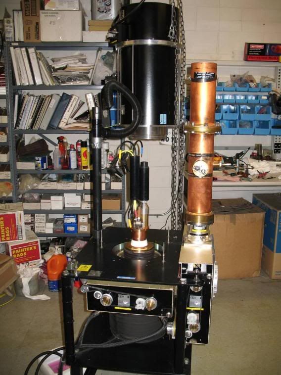
After dropping (e.g. carefully lowering) the new IOT in the magnet frame, the collector coolant hoses, first output cavity, second output cavity and output stack are bolted on. Lastly, the large cylindrical input cavity is lowered over the top.
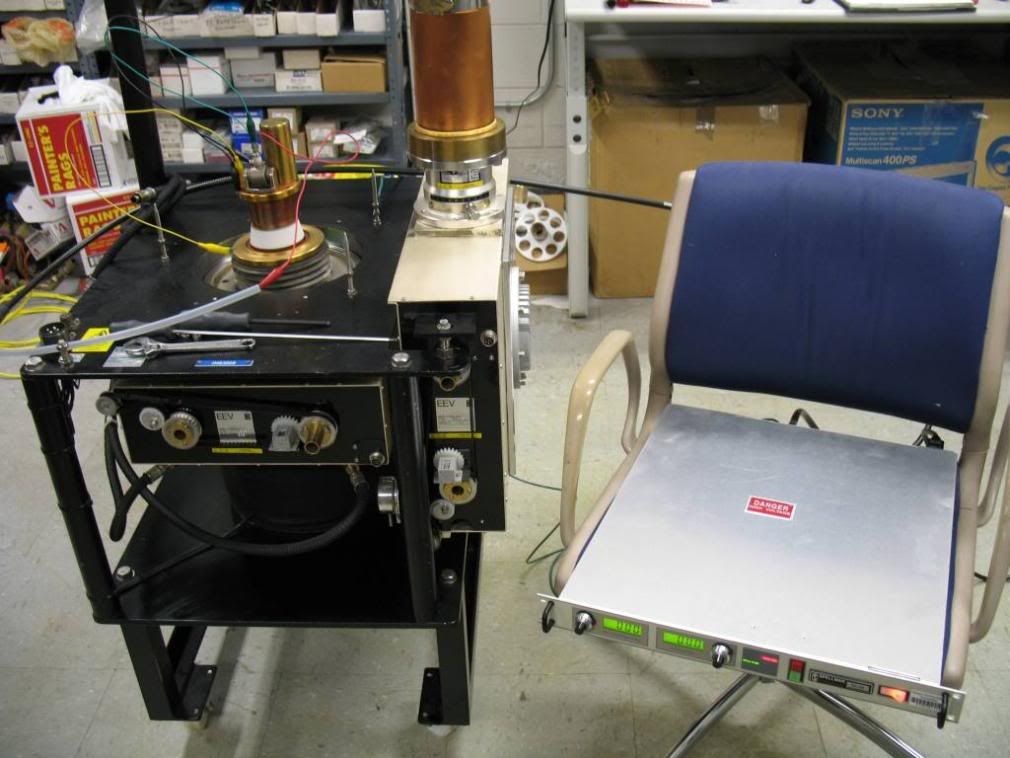
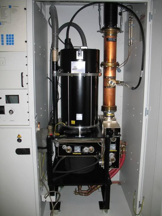
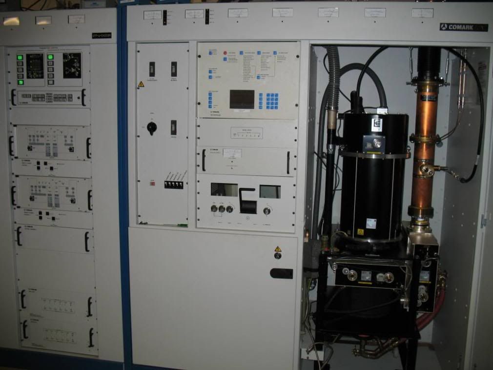
Now, we get to roll it back into the High Power Amplifier cabinet and get it ready to go back on the air! After reconnecting the electrical components, glycol coolant lines, RF output coupler to the various components we just assembled to the IOT and frame, this is what it should look like:
Now for the really fun part, sweeping the IOT for proper bandpass! This is sometimes done (almost always in the old days) by use of a device called a Tektronix 1405 sideband adapter that would inject a video signal into the transmitter exciter and through to the tube. Since our sideband adapter is an old piece of shit and didn’t work, our sweep was done by using the tracking generator function out of our Tektronix 2712 spectrum analyzer to shoot an RF signal through the solid-state amplifier section (after the exciter) and into the tube. This is a method I like best. Then we used a spectrum analyzer to monitor the signal from a sample port on the output stack to see how well the passband for this particular tube looks. Since this station runs on channel 65 the test gear is hooked up to sweep and monitor channel 65 and the controls on the output cavities and couplers are manipulated to provide proper bandpass and linearity for that channel.
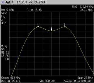
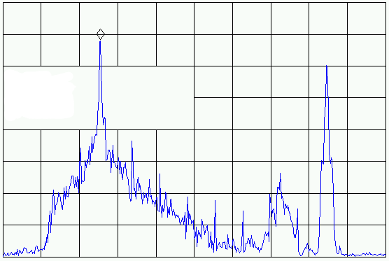
Not only does this maximize power output from the tube and ensure that the visual or aural carrier are not unduly suppressed, it also helps to minimize harmonics that are generated by the sound carrier at plus and minus 4.5MHz.
After sweeping the tube it’s time to phase balance it with the other HPA cabinet and put it on the air so it can earn its money. Time for a nap…