
All across the nation there are TV stations headed toward the analog shutdown mandated by congress on February 17th, 2009. At which point, only the station’s high power digital transmitter will be authorized to stay on the air along with the Class ‘A’ and low-power TV stations and their low-power translators (for the moment).
So, until that happy day arrives and the engineers can toss a hand grenade in the analog transmitter cabinet and run out the building laughing we need to keep these antiques running. This is one such story…
For broadcast engineers in the TV field this post will likely seem dull, simplistic and old-hat, but for those reading this and still curious, this is one of the many about-to-be-retired transmitters out there that bring analog television from the studio and push it out over-the-air to someone’s rabbit-ear antenna.
The company I work for at the moment has about 60 TV stations with high-power analog transmitters around the country and almost all have a companion DTV transmitter either co-located at the same site or at a new, more practical site. This station, serving the Sacramento market, has an old Varian TVT klystron transmitter that uses one klystron for the aural carrier and one for the visual carrier.
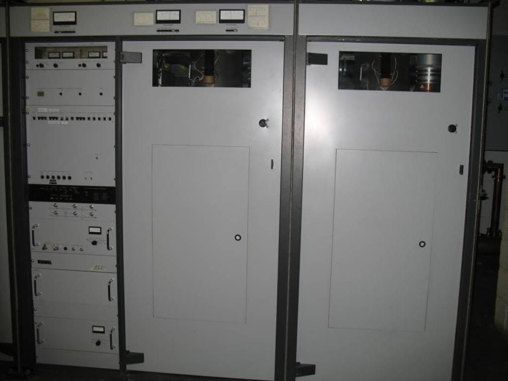
This channel 29 UHF 60kW TPO transmitter was installed around 1988. At 20 years-old, that really puts this old thing at its end-of-life and with the visual klystron having been in service since about 1992 (as far as we can determine), and approximately 140,000 hours – 40,000 longer than the tube’s expected life span, it has really paid for itself many times over. The aural klystron used to be the original visual klystron and has far more hours on it, but since it is the same model tube, only running at 1/10th the output power of the visual, it can run a lot longer since it just idles along making FM sound.
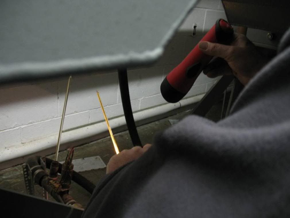
The first step after shutting it down, and making sure the 28kV power supply has discharged, is to clean it! High voltage inside the cabinets attracts dust as charged particles so rags of soapy water are needed for the cabinet and lint-free rags soaked in denatured alcohol are used on everything else.
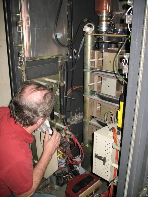
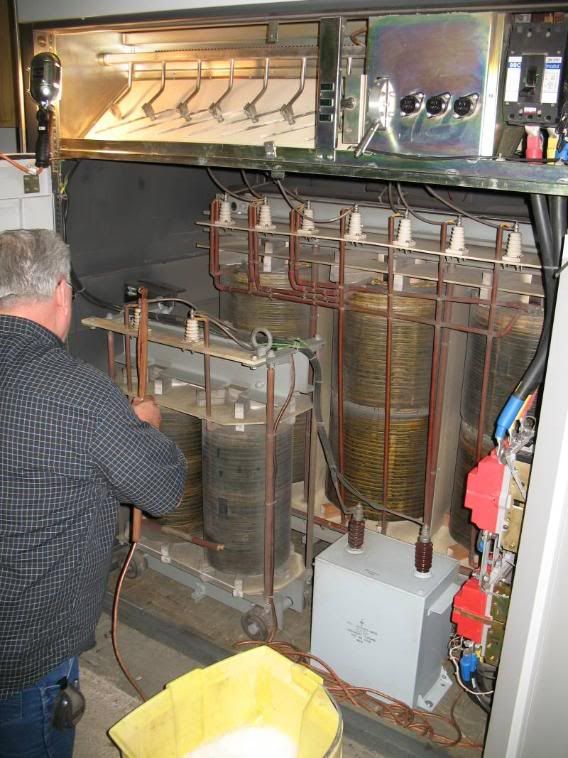
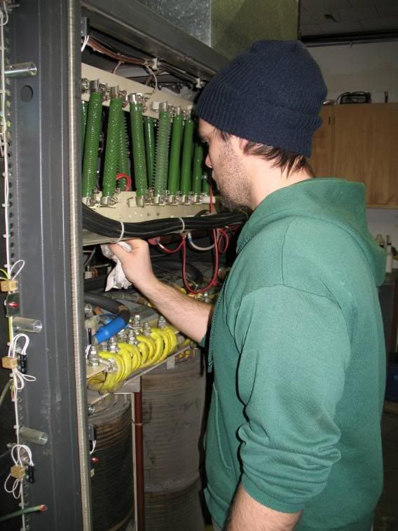
After everything is carefully cleaned it is easy to spot leaks, broken wires or anything else out of place. It is also necessary to prevent the high voltage needed to operate the klystron from arcing to other components or to ground.
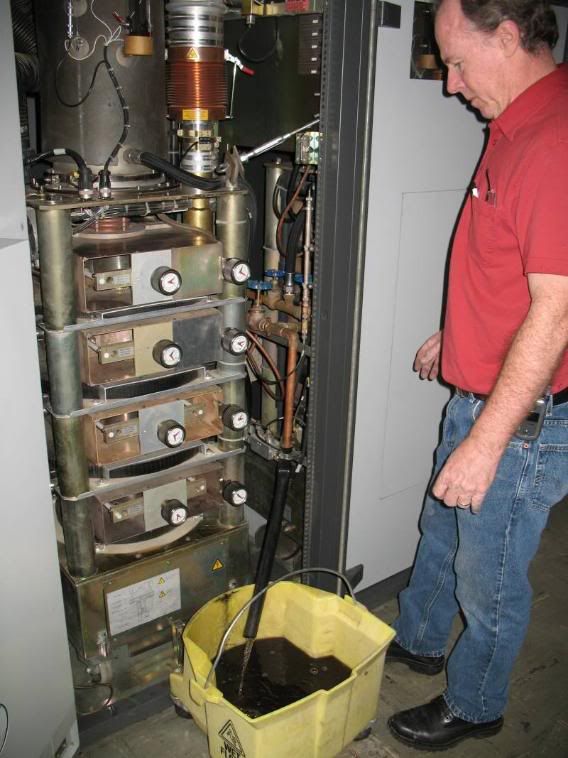
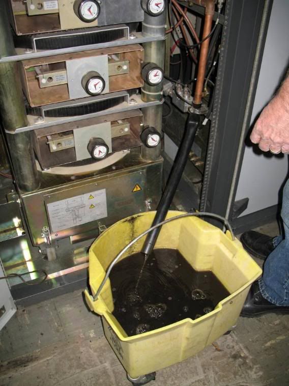
These old “steamer” klystron rigs use simple, distilled water to keep them cool (relatively) during operation. The water actually boils off as steam and travels outside to a “heat exchanger” where the steam is passed across a series of fan-cooled coils and is condensed back into cool water and returns to the klystron to boil off again. Since the pulsed klystron is only about 15% – 20% efficient, this means that all the other power in the beam is reduced to waste heat and boiled off. This poor efficiency is what spurred the short-lived MSDC klystron and the more popular IOT. The water-cooled copper head of the klystron creates a lot of carbon that needs to be regularly flushed from the system – like today.
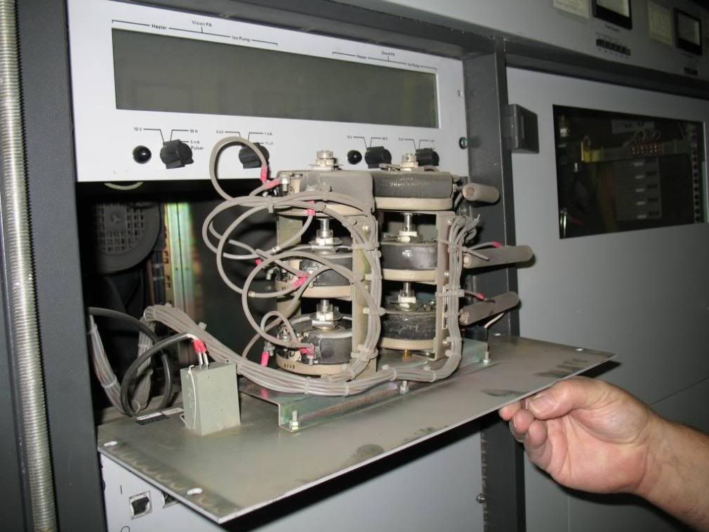
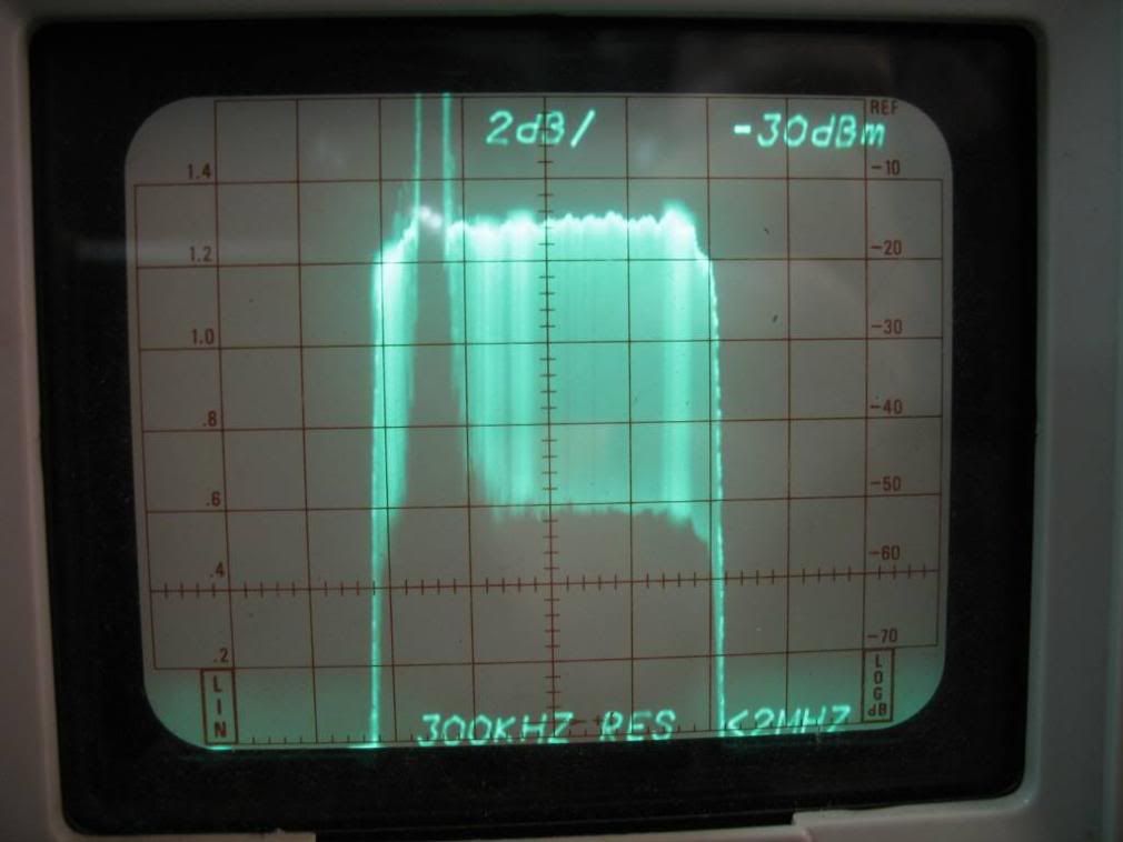
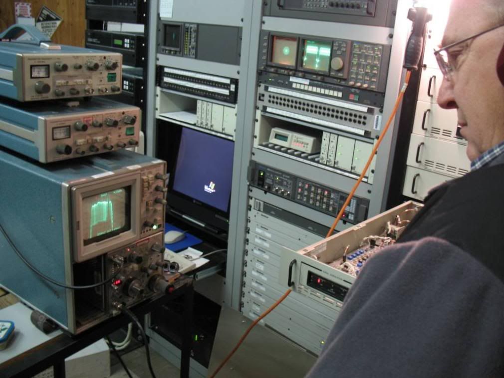
After the clean-up is complete it is time to sweep the tubes and ensure proper bandwidth and linearity. As the tubes get older their efficiency drops steadily, so the tuning is tightened up or “narrow-banded” to increase gain at the expense of frequency response. Because we know this tube is old and replacing it is an expensive proposition we basically “massage” the tuning of the tube to get the performance we need while sacrificing as little “ideal” performance as we can get away with and still broadcast a legal signal.
Now that that is done, it’s time to turn off the aural carrier and use a Tektronix 1405 Sideband Adapter to push a pure black video signal, with no color burst and no black set-up, through the transmitter to maximize carrier deviation and calibrate its true output power – because the meters always lie!
As it turned out the power meter on this transmitter was running a bit high and needed to be adjusted a bit. Since this rig uses a water-only coolant (not a water-glycol mix) the formula for determining the peak power is to use this formula:
Peak Power = 0.264 x ?T°C (difference in the dummy load’s in and out temperature in Celsius) x Flow Rate (in Gal/Min) x 1.68
For determining average power you can leave off the “x 1.68”, but the transmitter meters typically read peak.
Performing calorimeter measurements are very accurate, but they are a pain in the ass, take a bit of time and become more complicated when using a water-glycol mix. Once we know what the calorimeter power cal is we use a digital power meter off a sample port of the diplexer’s output and record that reading. Now we can very easily connect a meter, run the all-black signal and know what the actual power output is in a minute without going through the colorimeter process.
After the transmitter meters are calibrated we calibrate the transmitter remote control so that the remote metering matches what we see on site.
Now that that’s complete, we move to the exciters that feed the transmitter and go through a complete alignment using various test signals and working through the exciter trays to adjust for diff-phase, diff-gain, ICPM and proper depth of modulation. This is where Tim Mance comes in. Tim is the Chief Engineer of our company’s station in the Portland, Oregon market and not only has extensive experience with klystrons, but has the same exciters at his station and is able to fly right through the alignments that would have taken myself and the local Chief at least twice as long as we familiarized ourselves with the location of the exciter adjustment points. There’s a lot to be said for having good technical experience.
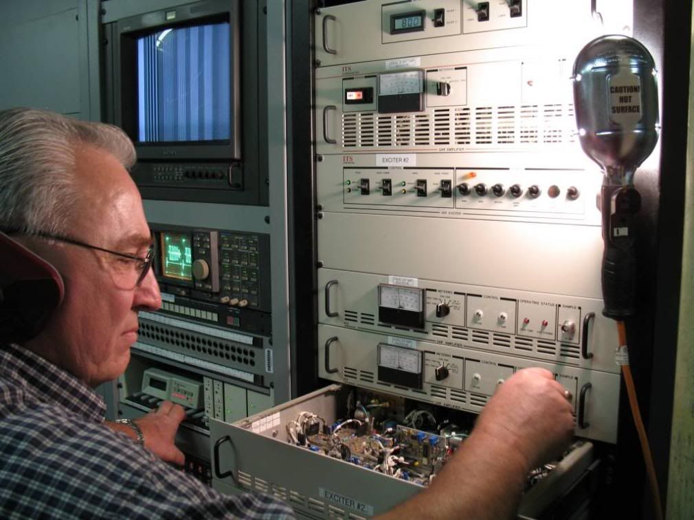
These exciter’s are not the original exciters that shipped with the transmitter. They are actually ITS exciters (before ITS sold to Axcera) that are far more adjustable and reliable than the originals.
Once the alignments are complete it’s ready for us to put normal programming into the transmitter and re-route the system so it is sending it’s signal into the antenna and over the air instead of into the dummy load as we had it for the adjustments and measurements.
Now, it’s time to go home.